


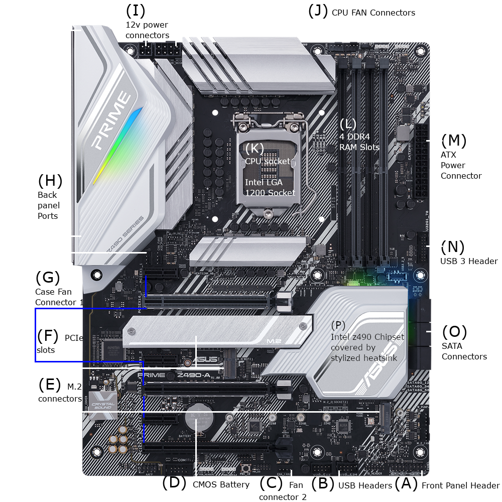
A motherboard is a large circuit board that facilitates the connection and communication of the essential components of a computer. Virtually all general purpose computers will have a motherboard. Below is an image of a motherboard with the important parts labelled. The motherboard shown is an Asus Prime Z490-A. Asus is the brand and Prime Z490-A is the model. The model is named after the Intel Z490 chipset that is used on the motherboard.
Starting from the bottom left and working our way to the right, we have the front panel header. The manual for this particular motherboard calls it a system panel header. In general, a header is a male connector that is made up of a set of metal pins. The front panel header on a motherboard is used to connect the power button LED, storage device activity LED, and internal speaker. This specific motherboard also has an intrusion connector. An intrusion sensor can be mounted on the computer case. If the case is opened, the sensor will send a signal that is logged. When the computer is booted, it will display a notification that an intrusion was detected.
To the left of the front panel header are USB headers. The USB ports on the outside of the case are connected to the USB headers on the motherboard. Some USB ports are mounted directly on the motherboard and some USB ports are connected to the motherboard through these headers. There are multiple USB specifications. These USB headers allow the connection of USB 2.0 ports. There are other headers on this motherboard that allow the connection of USB ports that follow the 3.1 and 3.2 specification.
To the left of the USB header is a case fan connector. Case fans are used to control air flow through the case to cool the computer. If you have really good eyes you may notice the label on the motherboard says CHA_FAN2. If you guessed that there is a CHA_FAN1 connector, you’d be right. It is the other labelled fan connector. It is above the highest PCIe slot.
If you look left of the case fan connector, there is a battery. This is a CMOS battery. This battery provides power to memory that holds important information such as the system date, time, BIOS password, and setup parameters. Sometimes it is necessary to reset this information. Resetting can be achieved by either using a jumper or removing the battery. A jumper is a small passive device that houses a conductor. To reset the system information, it is placed on a header that causes a short circuit.
Next we will go over the M.2 slots. M.2 is a relatively new connection standard. I will go into a bit more detail on this aspect of the motherboard. There are three M.2 slots on this motherboard. The visible M.2 slot in the lower middle area of the board is for a WiFi card. It is actually labelled on the board as M.2(WIFI). Note there is 1 screw hole to the left of this M.2 slot. Directly above the M.2(WIFI) slot is another M.2 slot. This slot is covered. The cover is labelled M.2. This slot is for an SSD. At the bottom right is another SSD M.2 slot.
General Information. Some general information about M.2 slots and modules. M.2 slots are typically used for connecting solid state drives. These solid state drives use an NVMe interface. M.2 slots are also used to connect WiFi adapters. Whether an SSD or WiFi adapter is used, the thing being inserted can be called an M.2 card or module. M.2 cards are all the same width but come in different lengths. Card sizes are 2230, 2242, 2260, 2280, 22110. The 22 stands for 22 millimeter width. The 30, 42, 60, 80, 110 stands for millimeter length. The cards are keyed differently. The key type is determined by which of the pins are notched. WiFi cards typically use key E and SSD use key B,M or B+M. B+M means the pins for both B and M are notched. This means a slot that is keyed B+M will work with both B and M cards. Remember, there are two compatibility factors for M.2 cards: the key type and the card length. While there are M.2 key adapter cards, try to find cards that are compatible with key and lengths supported by your motherboard.
Installation. To install an M.2 card, note the key type of the card and locate the matching keyed slot on the motherboard. Then insert the keyed edge of the card into the slot. The other end of the card has a mounting hole for a screw. The mounting hole on the card should line up with a screw hole on the motherboard. If the holes don’t line up, then the card is not compatible with your board. The M.2 slot on the bottom right of the Asus Prime Z490-A has multiple screw holes to support cards of different lengths.
From the bottom left up to the middle of the motherboard are 6 PCIe slots. The smaller slots are x1 and the larger are x16. The board shown has 3 PICe x16 slots and 3 PCIe x1 slots. A PCIe slot can be used to install various types of expansion cards. They are commonly used to install graphics cards, network cards (both wireless and wired), NVMe adapters (used to install an SSD), and USB cards (used for additional USB ports).
General Information. Some general information about PCIe. There are two important specs: the physical size of the PCIe slot and the version of PCIe supported by the card and the motherboard. There are 4 sizes: x1, x4, x8, x16. A card can only fit into a socket of its own size or greater. So a x8 card can fit into x8 or x16 slot, but it cannot fit into an x4 or x1 slot. As well as physical compatibility, the size determines the speed of data transfer. A greater size typically means greater transfer speed. There are currently 6 different versions of PCIe, however, version 6 has yet to see implementation by a manufacturer. The higher the version the greater the transfer speed. If a motherboard and card don’t support the same version of PCIe, the transfer speed will be limited to the lower of the two. So if the card supports version 2 and the board supports version 3, it will use version 2.
Above the highest PCIe slot is another case fan connector. This one is labelled CHA_FAN1.
Above the CHA_FAN1 connector is a large cover that says “Z490 Series” and in large letters “PRIME”. This covers the electronics for the back panel ports. The back panel ports are the ports that can be accessed via the back of the case. These include USB ports, a DisplayPort, an HDMI port, an Ethernet port, 5 analog audio jacks and 1 digital audio port.
At the top left are two 12 volt power connectors. One connector contains 8 pins and the other 4 pins. For this board, the 8 pin connector must be connected. The 4 pin is optional and may be used for additional power if overclocking the CPU.
If you look up and to the right, you will see the CPU fan connector. Because a CPU generates a significant amount of heat, it needs a dedicated cooler. There are different ways to cool a CPU. The most common is to use a fan mounted on a heatsink. A heatsink is a passive (no power is used) device. It is mounted directly over the CPU. Before the heatsink is installed a dab of thermal paste is placed on top of the CPU. The thermal paste helps transfer heat from the CPU to the heatsink. On the heatsink, a fan (or multiple fans) is installed. The fan moves the heat from the heatsink to the air in the case. The rear case fan should move the hot air from the inside of the case to the outside of the case. In a different article, I will describe how to install the case and CPU fans.
In the middle of the board is the CPU socket. There are multiple socket types from both AMD and Intel. Your CPU must be compatible with CPU socket on your motherboard. The board shown has an Intel LGA 1200 socket.
Installation.To install your CPU, you should refer to the motherboard manual. The instructions that follow are for this particular motherboard. On the CPU socket, there is a lever and a retention plate that need to be lifted out of the way. First lift the lever toward the back of the board then the retention plate towards the back of the board. Now install the CPU. Be careful at this step! Installing the CPU with the incorrect orientation will ruin the CPU. Most modern CPUs will have an arrow printed in one of its corners. The manual for this board indicates the CPU arrow should be placed in the front left corner of the CPU socket. In addition, it shows indents on the perimeter of the CPU that should line up with indents on the perimeter of the socket. The CPU should sit flatly in the socket. Before lowering the retention plate and level, make sure the CPU is oriented per the motherboard's instructions. Lower the retention plate. Finally and carefully lower the lever. Once the lever is parallel with the board, it should be locked in place by placing it under the arm on the CPU socket.
Below the CPU fan connectors are the RAM slots. This board has 4 RAM slots that support DDR4 DIMMS.
General Information. DIMM stands for dual inline memory module. This means that the memory modules have electrical pins on both sides of the module that allows for 64bit data transfer. RAM stands for random access memory. RAM is a type of volatile storage. In this context, “volatile” means that what is stored only persists as long as the RAM has power. This differentiates it from magnetic hard drives and solid state drives. Data stored in these hard drives and solid state drives persist without power.
Installation. Installation of DDR RAM is relatively simple. First identify which slots you should use. The motherboard manual should provide this information. The correct slots will depend on the total number of available slots and how many DIMMs are being installed. Normally you want to install DDR DIMMS in pairs. If DIMMS are not installed in pairs, then the data transfer rate will be lower than it would be if a pair was installed. There are latches on both sides of each RAM slot. Open the latches. Notice the divot in the DIMM module between electrical contacts. Now notice that the RAM slot is divided into two sections. The divot on the DIMM module should line up with the divider on the RAM slot. Once aligned, press the DIMM into the slot. Once the DIMM is fully seated, you should hear a clicking sound, and the latches will close to secure the DIMM in place.
To the right of the RAM slots is the ATX power connector. The main ATX power connector from the power supply is connected here. ATX stands for advanced technology standard. It specifies many different aspects about motherboards, power, and case dimensions.
As noted above, this is the USB 3 header on this motherboard. It allows the connection of USB ports that follow the 3.1 and 3.2 specification.
Below the RAM sockets on the perimeter of the board are the SATA sockets. SATA stands for serial advanced technology attachment. SATA is the physical interface that connects storage drives to the motherboard. It is a one-to-one interface. This means one drive per socket on the motherboard. This board has six SATA sockets. That means this board can accommodate up to six internal drives. Only the top three SATA sockets can be seen in this photo. The remaining three are directly below the three visible connectors. SATA drives need two connections to function. One is a power connection. The power connection uses a cable from the drive to the power supply. The other is a data connection. The data connection uses a cable from the drive to the SATA socket on the motherboard. These two cables are physically different so there isn’t much risk in mixing them up. The power cable simply won’t fit in the data socket and vice versa.
To the left of the SATA sockets is the chipset. On this board, the chipset is covered by a heatsink. The chipset is an extremely important part of the motherboard. It manages the data transfer between the motherboard components.